448
Level 3
Advanced Topics
Fig. 17b
Extruded meniscus (arrows)
6. Artifacts
MSK imaging must contend with the same artifacts as general
imaging, including acoustic shadowing, through transmission (en-
hancement), refraction, and ring down or reverberation artifact.
Additionally,becauseMSK often deals with imaging specular reflec-
tors, another artifact not often discussed in general imaging, called
anisotropy, becomes relatively prevalent.
6.1 Shadowing, Enhancement, and Anisotropy
Anisotropy:
By definition,a tissue that demonstrates different prop-
erties dependent on the angle of viewing is said to be anisotropic.
Unlike the liver or other soft tissue parenchyma which displays an
isotropic pattern regardless of angle of insonation,tendons,
15
nerves,
ligaments, and to a certain degree muscle will portray a different
reflective property dependent on insonation angle. The degree of
change of reflectivity is largely dependent on four factors:
1.
the surface geometry relative to the wavelength
2.
tissue composition of structure
3.
the incident angle
4.
the depth of the insonated structure
As discussed in detail in Chapter 3, the type of reflection is greatly
determined by the surface characteristics relative to the wavelength.
When the surface is large and smooth relative to the wavelength
specular reflection occurs. Anisotropy is the effect caused by the
angle dependence of special reflection. The tissue composition de-
termines the acoustic impedance as well as the rate of absorption. As
the difference in acoustic impedance between the specular reflector
and the surrounding tissue increases, the percentage of reflected
energy increases, decreasing transmission. For example, bones
tend to be both very absorptive and highly specular in reflection.
Consequently, bone when surrounded by normal tissue, results in a
very bright reflection and usually an inferior acoustic shadow. Water,
blood, and synovial fluid are acoustically homogenous relatively (of
uniform acoustic impedance) and therefore tend to through trans-
mit more of the energy, resulting in less attenuated inferior images,
commonly referred to as enhancement (as commonly seen inferior
to cysts and blood pools). Reiterating a point made in Chapter
3 and Chapter 6, assuming the absence of imaging artifacts, the
best incident angle for B-mode imaging is zero degrees (when the
beam direction is perpendicular to the reflecting surface also called
“normal incidence”). As the incident angle deviates from normal, a
proportionate amount of returning energy does not reflect toward
the transducer, becoming more significant with increasing depth.
Two structures of similar composition but at different depths will
show varying degrees of anisotropy.Conversely,structures of differ-
ent compositions but at equal depths may show less change.
Figure
19
demonstrates two views of the flexor tendons of the wrist with
varying incident angles. The greater the angle (away from normal
incidence) the less energy returns from the tendons ultimately
resulting in a void of return signal, or dark area.
Significant errors can be made in diagnosis if 90 degree incident
angle is not maintained.Constant realignment of the incident beam
to the target anatomy is imperative to correctly identify the true
reflectivity. “Rocking” the transducer in short-axis to the anatomy
or “heel-toe” the transducer in long axis to target anatomy will
greatly reduce the probability of error. Graded compression used in
conjunctionwith“rocking”and“heel-toe”are conventional scanning
techniques used to minimize errors of reflectivity.
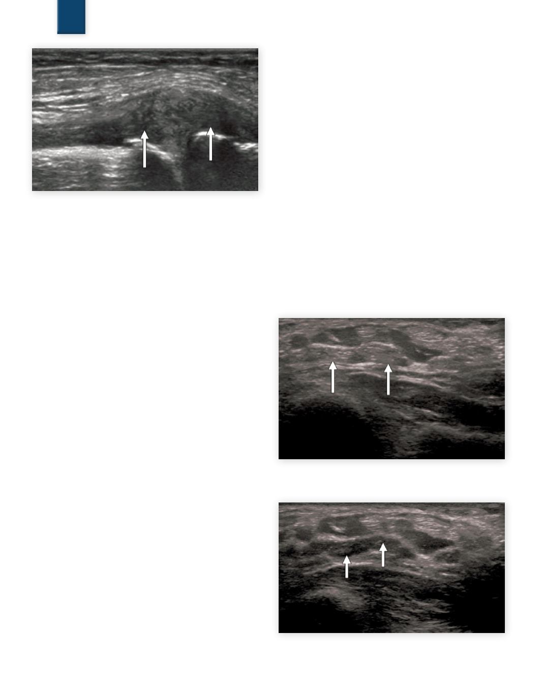
Fig. 18a
SAX profunda flexor tendons with normal reflection
with 0 degree incident angle (arrows)
Fig. 18b
SAX profunda flexor tendons with 30 degree in-
sonation angle illustrating anisotropy (arrows)
SAMPLE PAGE


