92
Level 2
Board Level
14. Bandwidth
14.1 Bandwidth Defined
In recent years,there has been considerable talk about bandwidth in
just about every arena of life. We hear about cell phone bandwidth,
cable television bandwidth, digital satellite bandwidth, internet
bandwidth, etc. There is also considerable talk about bandwidth
in ultrasound.
Specifically, bandwidth is defined as the useful range of frequencies
over which anything can operate. There are many different types
of bandwidth. There is transducer bandwidth, transmit bandwidth,
receive bandwidth, system receiver bandwidth, display bandwidth,
etc. In general, you must specify the bandwidth to which you are
referring.
KEY CONCEPT
14.2 Pictorial Representation of Bandwidth
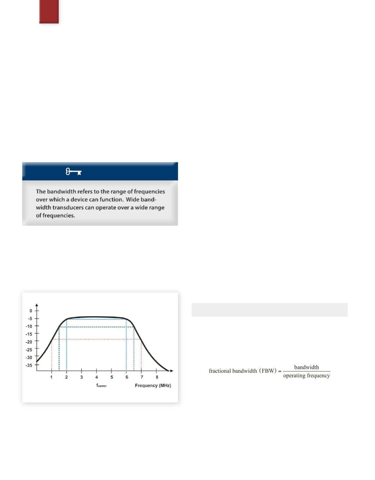
Figure 26
represents a graph of a transducer bandwidth. Notice that
the horizontal axis represents increasing frequency and the vertical
axis represents the response sensitivity or signal amplitude. For this
graph, the sensitivity is specified in decibels.
Fig. 26
Bandwidth
From this graph, we see that at frequencies below 2 MHz there is
relatively little sensitivity. Similarly, at frequencies above 6 MHz
there is little sensitivity. But how sensitive is sensitive enough? To
discuss bandwidth accurately,the attenuation points must be speci-
fied as demonstrated below.
The 6 dB bandwidth point is the range of frequencies that exist be-
tween the two corner frequencies at which the signal sensitivity is
decreased by 6 dB. For the above example, the signal has decreased
by 6 dB at 6 MHz and at 2 MHz. The 6 dB corner frequencies are
6 MHz and 2 MHz. Since there is a range of 4 MHz between these
two corner frequencies, we would say that the 6 dB bandwidth is
4 MHz, or:
-6 dB bandwidth = (6 – 2) MHz = 4 MHz.
Similarly, the 10 dB bandwidth point is the range of frequencies
that exists between the two corner frequencies at which the signal
sensitivity is decreased by 10 dB. For the above example, the signal
has decreased by 10 dB at 6.4MHz and at 1.6MHz. The 10 dB corner
frequencies are 6.4 MHz and 1.6 MHz. Since there is a range of 4.8
MHz between these two corner frequencies, we would say that the
10 dB bandwidth is 4.8 MHz, or:
-10 dB bandwidth = (6.4 - 1.6) MHz = 4.8 MHz.
For engineering purposes, we will generally specify at least two or
three different bandwidth points,so as tomore accurately character-
ize the response of the systemwe are measuring. For completeness,
see if you can derive the 20 dB bandwidth and corner frequencies
from the graph in
Figure 26
.
-20 dB bandwidth = (7 – 1) MHz = 6 MHz
14.3 Bandwidth Calculation
From the above example,we see that the bandwidth is defined as the
maximum corner frequency minus the minimum corner frequency
for a specified attenuation rate, or:
bandwidth (BW) = maximum frequency - minimum frequency.
14.4 Fractional Bandwidth
For transducers, a much more commonly used metric is the frac-
tional bandwidth. As the name suggests,the fractional bandwidth is
determined by dividing the bandwidth by the operating frequency.
Consider
Figure 26
assuming that the operating frequency is the
same as the center frequency,
f
c
, the 6 dB fractional bandwidth
would be (4 MHz / 4 MHz) or 100%. Note that the 4 MHz in the
numerator represents a range of frequencies,while the 4MHz in the
denominator represents a single frequency in the center of the band.
Transducers are considered to be broadband when they have more
than approximately an 80% fractional bandwidth. The bandwidth
in the figure would represent a broadband design.
SAMPLE PAGE


